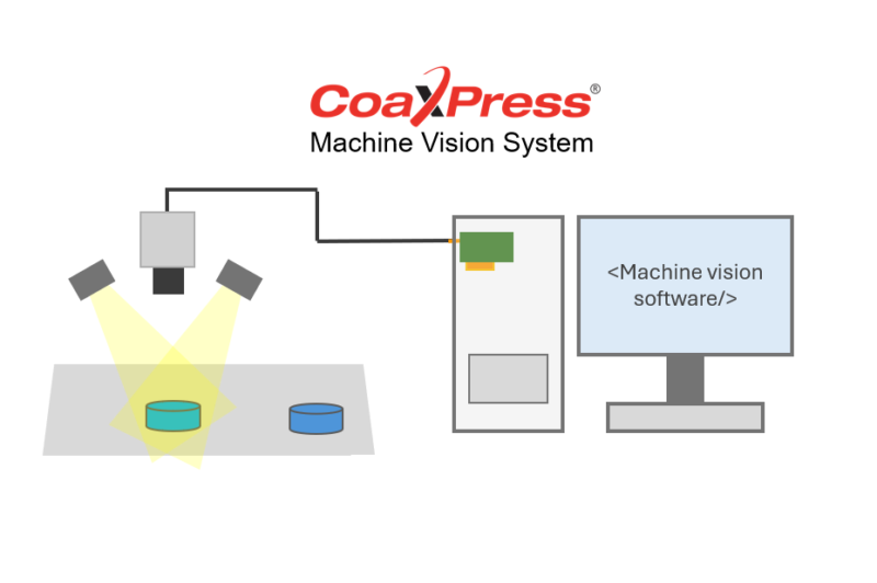
This article supports engineers looking to introduce a vision system based on the CoaXPress standard from the ground up. We explore what components to look for, how to get up and running, and how to troubleshoot common problems.
Understanding CoaXPress
CoaXPress (CXP) is an asymmetric, high-speed point-to-point serial communication standard for the transmission of video and still images. The standard is hosted by the Japan Industrial Imaging Association (JIIA) and the current version 2.1 was released in February 2021.
CXP enables high data rates (up to 12.5 Gbps per connection), long cable lengths (up to 35m at CXP-12 and 100m at CXP-3 using Belden 1694 cable), and power over coax (PoCXP), making it ideal for industrial environments with demanding speed, resolution, or distance requirements. More details on the standard can be found on our website, or on the official CoaXPress website.
Included in version 2.1 is the CoaXPress over Fiber protocol, enabling CXP to run over fiber cables and connectors. Using fiber optics for high-speed imaging has significant benefits where long cable runs are required, or cameras are placed in harsh electrical environments.
Selecting a CoaXPress Camera
When choosing a CoaXPress camera, engineers must consider several key factors. The resolution and frame rate must align with the application’s imaging requirements, for example, high-speed inspections typically demand cameras with resolutions between 5 and 25 megapixels and frame rates exceeding 100 frames per second. CMOS sensors are generally preferred due to their speed, low noise, and high sensitivity. Global shutters are often selected over rolling shutters for their ability to capture fast-moving objects without image distortion – you can read more about choosing between global and rolling shutters in our blog.
The lens must match the camera sensor’s format and resolution to avoid vignetting or optical distortion. Fixed focal length lenses are a good option for high image quality in controlled environments, and the focal length should be chosen based on the working distance and field of view required.
It is important to ensure that the camera complies with the appropriate CoaXPress version and supports the number of lanes required for the desired data throughput. Many high-performance cameras use two to four coaxial connections to achieve maximum bandwidth. Some models also support Power over CoaXPress (PoCXP) and are powered via the connection to the frame grabber, eliminating the need for separate power cables.
If the application requires synchronization and advanced triggering capabilities – one of the key advantages of CoaXPress – it is still important to verify that the chosen camera setup meets expectations in this area.
Choosing Machine Vision Lighting
When selecting lighting, it’s important to account for the working distance and the size of the field of view, as these directly influence the intensity and uniformity of illumination required. A larger field of view or greater working distance typically demand brighter or more focused lighting. Optical considerations, such as the surface reflectivity, texture, and geometry of the target object will also impact the choice of lighting angle and type.
Choosing between a color or monochrome camera matters too: monochrome cameras are more sensitive and work well for narrow-band lighting for high-contrast imaging, while color cameras require broad-spectrum or white light for accurate color reproduction. The lighting setup should also reflect the application’s goals – whether detecting fine surface imperfections like scratches or dents, reading printed text or codes, measuring dimensions, inspecting silhouettes, or recognizing objects based on shape or color patterns.
Environmental conditions are another key factor; in environments with variable or strong ambient light, shielded lighting or enclosures may be needed to maintain consistent imaging. Consistency and control over lighting are essential to ensure reliable, repeatable inspection results in real-world production settings.
To accommodate different setups and the individual challenges of each, different lighting types are available:
Ring Light: Provides even, shadow-free lighting around the lens. Good for general inspection and reflective surfaces.
Bar Light: Directional lighting ideal for highlighting textures, edges, or defects by casting shadows.
Dome Light: Soft, diffuse light that minimizes glare, perfect for shiny or curved surfaces.
Strobe Light: Delivers intense, short bursts of light synchronized with the camera’s trigger – ideal for freezing motion in high-speed inspections.
Coaxial Light: Directs light along the camera’s axis for glare-free imaging of flat, reflective surfaces.
Fiber Optic Light: Useful for illuminating complex shapes with shaded or hidden areas.
Spotlights: Very focussed illumination for highlighting specific areas of interest.
Backlighting: One of the light sources listed above may be placed behind the object to create silhouettes for edge detection or shape inspection, and to minimize specular reflection of smooth or shiny surfaces.
Matching the wavelength of the light to the material properties of the target can enhance contrast and reduce noise. For example, a decision between monochrome or color may be simple, but applications such as food processing or recycling sorting may benefit from SWIR or hyperspectral cameras.
For dynamic or high-speed applications, strobe-capable lighting synchronized with the camera trigger ensures consistent illumination. Systems requiring fine control over exposure often benefit from adjustable-intensity lighting or external lighting controllers.
Whatever lighting solution is selected, be sure to prototype lighting setups under actual environmental conditions.
Selecting a Frame Grabber
A frame grabber, or acquisition card, is a device that enables high-speed image capture by efficiently transferring images from cameras to computers for processing. It serves as the interface between the CoaXPress camera and the processing computer.
The frame grabber must provide the number of input channels used by the camera or cameras and support the relevant CoaXPress version. For multi-camera setups, some frame grabbers offer the ability to acquire from and synchronize several cameras simultaneously, which is vital in volumetric, 3D or stereo vision systems.
The grabber should support highly reliable direct memory access (DMA) for efficient data transfer to the host PC and provide comprehensive general-purpose input/output (GPIO) ports for triggering and synchronization. A robust frame grabber is essential to maintain data integrity during the demanding 24/7 operation of many industrial applications.
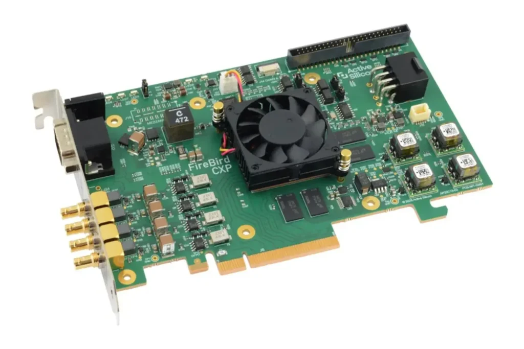
Active Silicon provides a range of FireBird CXP frame grabbers offering up to 8 connections of 12.5 Gbps each, and CoaXPress over Fiber (CoF) options. They are all fully GenICam compliant, support GPU processing and demanding real-time triggering requirements e.g. for line scan applications or multi-camera setups.
FireBird frame grabbers come with our ActiveSDK software development kit which provides comprehensive example applications and optimized libraries. Camera and frame grabber control is delivered by our GenICam compliant front-end software, ActiveCapture. Third party machine vision software is also supported.
Selecting a PC or Machine Vision Computer
System performance depends on a powerful PC at its heart. A machine vision computer should include at least a quad-core Intel i7 or Xeon processor, especially if real-time image processing or decision-making is required. Systems using AI or deep learning models may benefit from a dedicated NVIDIA GPU. RAM requirements depend on the size and rate of image acquisition, with 16GB as a minimum. High-speed SSDs are recommended to avoid bottlenecks during data storage. Importantly, the motherboard should provide a PCIe x8 or x16 slot for the frame grabber.
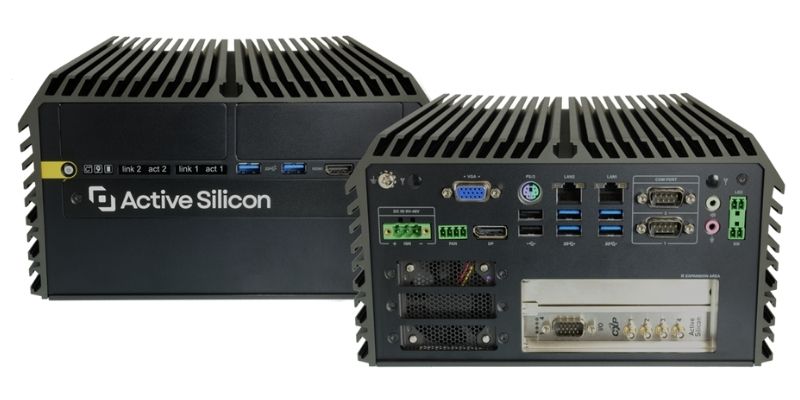
In space-constrained or industrial environments, integrated machine vision PCs such as the Oncilla Machine Vision Computer – CoaXPress offer compact, rugged computing with an onboard frame grabber and processing unit. It features a 12th generation Intel Core i7 Series processor, 2x DDR5 SO-DIMM sockets and 2x PCIe expansion slots (both freely available as the frame grabber is integrated). It supports 16GB of DDR4 memory with expansion up to 64GB. Incorporating a FireBird CoaXPress Frame Grabber, preinstalled operating system and equipped with camera/frame grabber control software and an SDK, an Oncilla computer produces a complete machine vision system. It is available with either a FireBird Quad CXP-12 Frame Grabber or a FireBird CoaXPress over Fiber 4xCOF-12 Frame Grabber.
Designing the Software
SDKs supplied with most frame grabbers typically include APIs to configure camera settings, acquire and buffer images, and control triggering. Most provide sample code in C++, C#, and increasingly Python, to simplify integration.
Custom software offers the greatest flexibility and is suitable for systems requiring integration with robotics, programmable logic controllers, or custom machine learning models. However, it comes with a higher development cost and complexity. Alternatively, vision libraries like Halcon, MATLAB, Cognex VisionPro and others accelerate development and are often sufficient for standard inspection tasks. Using GenICam-compliant cameras can simplify software development by providing a common interface regardless of camera vendor.
Active Silicon’s acquisition cards are compatible with a number of leading third party applications. We also offer custom-designed software through our team of highly experienced software specialists, services include:
- Kernel drivers for several operating systems
- Libraries / API design and implementation
- Graphics display: DirectX, OpenGL, CUDA
- GUI application design (Qt, C# / WPF)
- GenICam / GenTL
- Application software for custom embedded systems
Getting Up and Running
Once the components are selected and the system is assembled, commissioning can begin. This starts with physically mounting the camera and lighting, installing the frame grabber into the PC (or connecting the machine vision PC), and connecting the coax cables. If PoCXP is not used, the camera will also need an external power supply. Additional connections for triggering or encoder inputs may be required, especially in systems synchronized with conveyor belts or robotic arms.
After assembling the hardware, install the frame grabber drivers and SDK along with any camera vendor tools. Configuration begins with setting the correct pixel format, resolution, and acquisition mode on the camera. It’s important to test live image acquisition through the vendor’s viewer utility or your application software before proceeding further.
Next, tune the camera’s exposure settings and the lighting intensity to ensure clear, consistent images. Any strobing or triggering features should be synchronized to eliminate motion blur or inconsistent lighting effects. Once acquisition is stable, you can begin integrating image processing and analysis routines into your software.
Application software is installed after the hardware setup is complete and the basic system components (camera, frame grabber, lighting, and PC) are properly connected and tested. Machine vision libraries should be the first installation, as these libraries often form the foundation for image processing, analysis, and decision-making by other software.
There may be an element of troubleshooting to do in the initial set up as issues can arise. Frame loss is usually due to a PC bottleneck or misconfigured DMA; this may require optimizing memory settings or updating software. Noise or image tearing can result from signal degradation, particularly with long or low-quality coax cables, so shielded, high-spec cables are recommended. Lighting inconsistencies often trace back to flickering or unsynchronized strobes, which can be corrected by verifying trigger timing and using stable DC sources.
A Vision System for Today’s Demanding Applications
Deploying a CXP vision system offers engineers the speed, bandwidth, and reliability required for today’s most demanding industrial imaging applications. By carefully selecting each component, engineers can build a high-performance vision system tailored to the exact needs of the application. With proper planning and thorough testing, CoaXPress can form the backbone of a robust and scalable imaging platform.
If you’re unsure where to start with system integration or need help choosing components, get in touch with our team.